Using 690V for industrial low-voltage distribution networks to lower investment costs and improve network efficiency.
Summary
The most commonly used voltage in industrial facilities to power the low-voltage electrical distribution system is 400V, and in rare cases, 220V three-phase.
This level is widely used because it's the same voltage used for the public electricity distribution network, so equipment, appliances, and components are readily available on the market.
However, adopting a higher voltage level presents certain advantages, mainly in terms of investment cost savings and improved network efficiency; this could make this choice quite interesting and practical.
To verify the above statement, a detailed analysis was carried out during the basic design of the electrical system for a new industrial facility, characterized by a total consumption of around 180 MW, of which 40% is powered at the low voltage level.
The goal of the analysis was to demonstrate the suitability of 690V for the low-voltage distribution/utilization system, compared to 400V.
From knowledge of usage loads, a detailed comparison was made between the two alternative solutions, focusing in particular on the following key points:
- Size and cost of induction motors;
- Maximum load current and breaking capacity of available switching devices on the market;
- Voltage drop and cable cross-section;
- Sizing and number of power transformers;
- Power losses.
The article provides an overview of the approach used in the study and presents several examples related to the analyzed facility.
Numerous tables facilitate, for each of the analyzed factors, the comparison between the two solutions and make it easier to analyze the results.
The study identified the size and number of motors as the key factors that could lead to replacing 400V with 690V and thus defined general criteria that can be used for any specific facility.
Introduction
The most commonly used voltage in European industrial installations to power the low-voltage electrical distribution network is 400V, and in rare cases, 220V three-phase.
This voltage level is widely used because it's the same as that used for the public distribution network, so equipment, appliances, and components are easily available on the market.
The 400V voltage level is generally associated in industrial installations with 6000V to power medium-voltage users, typically motors. Using these two voltage levels allows for the installation of well-tested equipment and machines with standardized characteristics, which can be supplied by a large number of manufacturers.
However, adopting a higher "low voltage" level (i.e., 690V) offers certain advantages that could make this choice quite interesting and practical; the main advantages concern investment cost savings and improved overall network efficiency.
Several key factors need to be considered to compare the two alternatives (i.e., 690 and 400V), namely:
- Size and cost of induction motors;
- Maximum load current and breaking capacity of available switching devices on the market;
- Cable voltage drop under normal operating conditions and during motor start-up;
- Cable cross-section;
- Sizing and number of power transformers;
- Total power losses.
All of the above elements were analyzed in depth during the basic design of the distribution system for a new integrated gasification combined cycle (IGCC) power plant, characterized by a load consumption of around 180 MW, of which 40% are motors powered at the low-voltage level.
The objective of the study was to verify the actual convenience of using 690V instead of 400V, taking into account the impact on the market; the results allowed for the statement of some general rules that can be used for any specific facility.
Description of the IGCC Plant
The plant is a future IGCC, characterized by a generation of 980 MW of electrical energy, by burning the synthesis gas, obtained by gasification of refinery residual oil, in two gas turbines, assembled to form a combined cycle. The chemical process is based on partial oxidation of the carbon content of the raw material, with pure oxygen and HP steam (as raw material atomizer and reaction moderator), producing a synthesis gas rich in CO and H2.
The oxygen is obtained by air distillation from a cryogenic plant installed inside the complex.
The synthesis gas exiting the gasifiers is treated and cleaned to be fed to the gas turbines of the combined cycle.
The complex requires a load demand of around 180 MW, including the auxiliary service of the combined cycle. The majority of the load (about 130 MW) is related to the air distillation plant, to obtain the oxygen, characterized by two trains each comprising three very large motors (air compressor - 30 MW; nitrogen compressor - 25 MW; oxygen compressor - 10 MW).
The remaining loads are related to three main processing units, namely the gasification unit, the utility unit common to the entire plant, and the combined cycle unit.
They are characterized by different sizes of induction motors as indicated in the table below.
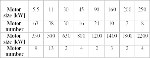
Size and number of motors installed in the three main processing units.
Analysis of Key Points
Induction Motors
One of the key points in the comparison between 400V and 690V is the investment cost of induction motors.
On the European market, 690V motors are available in the range of 0.18 to 1000 kW with a totally enclosed fan-cooled construction and up to 630 kW with a protection type of EEx-d, EEx-e, Ex-n for hazardous areas (EEx-p for larger motors).
It's common in industry to use 400V motors up to 160-200 kW (if there are no particular conditions) to keep the voltage drop within acceptable limits during normal and starting conditions up to a distance of about 200 m; larger motors are powered at 6000V.
In general, the investment cost of 690V motors is the same as that of 400V motors; conversely, the investment cost of 690V motors is the same as that of 400V motors.
A 6kV motor is about two to three times larger than the corresponding size of a low-voltage motor.
Therefore, the higher the number of motors that can be powered at 690V instead of 6000V, the greater the saving in terms of investment cost.
To evaluate the saving in terms of investment cost, it's mandatory to establish the upper size of the motor that can be powered at 690V.
Distribution Panels and Switching Equipment
Low-voltage distribution panels are generally designed, with regard to dielectric strength, for a voltage of up to 690V. Therefore, standard-manufactured low-voltage distribution panels can be used either at 400V or 690V.
On the other hand, the short-circuit breaking capacity and the closing power of circuit breakers, motor starters, and any switching device are significantly reduced when the operating voltage increases.
In general, when used at 690V, the breaking capacity is reduced, compared to the corresponding nominal values of 400V, by the order of 65% to 75% for molded-case circuit breakers and 15% to 25% for air-break circuit breakers.
Furthermore, for the 690V level, manufacturers certify motor protection coordination (i.e., fuses and contactors, molded-case circuit breaker and contactors, limiters and contactors) only up to 50 kA and for a motor size up to 350 kW. Air-break circuit breakers with a higher breaking capacity can be used, but they are only available for motor starters above 300 kW.
Therefore, using 690V, the 50 kA breaking level must not be exceeded; this limitation does not exist for the 400V voltage level, although a breaking capacity of more than 50 kA is generally not recommended for good engineering practice.
With regard to motor starters, different solutions are possible. The molded-case circuit breaker-contactor combination is available up to 315 kW and 335 kW respectively for nominal voltages of 400V and 690V.
In the latter case, the molded-case circuit breaker must be of the current-limiting type, with an increase in investment costs of about 20%.
The fuse-contactor combination represents a less expensive solution than the molded-case circuit breaker-contactor combination (investment cost lower by about 40% to 20% from low nominal values to high nominal values) and offers a very reliable level of protection against short circuits, even for the highest fault functions. Again, coordination is ensured up to the same limits as molded-case circuit breakers.
For motors with a power greater than 355 kW, motorized air-break circuit breakers must be used for a voltage of 690V.
Cables
Low-voltage cables, rated 0.6/1 kV, can be used either at 400V or 690V without affecting the insulation strength.
With regard to the "ampacity" of cables, the use of 690V motors involving lower load currents than 400V, allows for a reduction in the cross-section of the cable conductors (keeping the same voltage drop in both cases) and cable power losses. Alternatively, the same cross-section can be used to power, with the same voltage drop, motors located at a greater distance or of a larger size.
The reduction in cross-section is true for motors with a power greater than 5.5 kW, because for smaller motors, the cable cross-section is determined, both for 400 and 690V, by the maximum power transmitted.
For motors above 200 kW, the use of 690V requires cables with a larger cross-section than in the case of motors of the same size powered at 6000V. Investment and operating costs are therefore higher, as the cost of the conducting material is predominant in the cost of cables.
Low-Voltage Transformers
The use of 690V instead of 400V implies the possibility of increasing the transformer's rated power. Its maximum value, however, is limited by the fault current duty on low-voltage panels and their switching devices and motor starters. Given that the figure of 50 kA must not be exceeded, including the motor contribution, the rated powers of low-voltage transformers must not exceed 3.15 MVA, with a short-circuit impedance no less than 6-7%.
Therefore, since numerous motors, generally powered at 6000V, must be powered at 690V, the number of low-voltage transformers must increase compared to those necessary for 400V. Furthermore, if the electrical scheme is organized in such a way that the low-voltage network is cascaded from 6000V, no reduction in the size of medium-voltage transformers is achievable.
Consequently, the increase in the number of 690V transformers implies an increase in both the investment cost and the power losses of the transformers.
It becomes more practical, where possible, to draw the 690V distribution system directly from the primary medium-voltage distribution network (i.e., 15 kV or 33 kV).
Upper Size of 690V Motors
The upper size of the motor to be powered at 690V can be individualized by setting, at the motor start-up, the same maximum voltage drop accepted for 400V motors (max 200 kW), also taking into account the equivalent impedance of the power transformers.
The calculations (table below) were performed assuming a cable length of 200 m and a motor starting current of 6.5 times the respective rated current.
The maximum permissible voltage drop of the assumed bus during motor start-up is 10%, with a voltage across the motor not less than 80% of the rated voltage.
According to the table, the upper limit of the size of the 690V motor is about 630–800 kW. Motors above these sizes must be powered at 6000V.
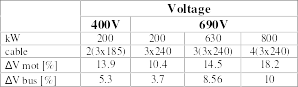
Voltage drop during motor start-up
Key Points Criteria Applied to the IGCC Power Plant
As a general rule, to compare the two alternatives (i.e., 400V and 690V), all the above considerations must be taken into account and quantified from an economic point of view. The investment costs of motors, motor starters, and network components must be evaluated as well as the capitalized power losses of cables and transformers.
For the specific IGCC power plant, the application of the above criteria is illustrated below.
The evaluation of investment costs must include:
- Motor departures, complete with motor, cable, motor starter, and switching protection device;
- Low-voltage transformers and transformer departures;
- Low-voltage panels, composed of two inlets and a coupling circuit breaker (secondary selective scheme).
Investment Cost of Motor Departures
The cost of the 400V, 690V, and 6000V motor departures is indicated in the table below, in reference to each motor size. The fuse and contactor combination was considered for the 400V and 6000V motors up to 1200 kW. The same arrangement was considered for 690V for motors with a power up to 250 kW; air-break circuit breaker for larger motors.
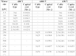
Investment cost of each motor power supply (fuse and contactor combination). (*) Air-break circuit breaker - 690V.
According to the table, the investment cost of 690V motor power supplies is 20% to 60% lower than that of the corresponding 6000V ones.
Considering at the first stage only motors with a maximum power of 800 kW (i.e., the upper motor that can be powered at 690V), the total investment costs of the motor power supplies of the plant are listed in the table below.

Total investment cost of motor power supplies up to 800 kW of the entire facility
Investment Cost of Transformers and Panel
A primary distribution system, operating at 33 kV, is used to power the three processing units of the plant.
In the case of 400V, it's necessary to provide a medium-voltage (6000V) secondary distribution system to power motors with a power greater than 200 kW. With the choice of 690V, provided that only motors with a maximum power of 800 kW are present, the 6000V level is not necessary.
To compare the two choices (i.e., 400V and 690V), it's necessary to determine the number of low-voltage and medium-voltage transformers necessary to power the total load. Referring to the specific case examined, each processing unit is powered by a suitable load center, whose electrical system is organized, for reliability reasons, according to the secondary selective scheme.
Considering only motors up to 800 kW, the 400–6000V solution requires two low-voltage transformers (2 MVA) and two medium-voltage transformers (4.5 MVA) for each processing unit, provided that there is a simultaneity and utilization factor of 0.6 and 0.9 respectively.
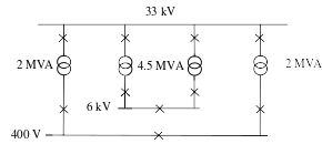
Simplified single-line diagram of each processing unit based on distribution voltages of 6 kV and 400 V.
To minimize transformer losses, the 400V system is directly powered by the 33 kV primary distribution system and not cascaded from the 6 kV system.
The simplified single-line diagram above of each processing unit based on distribution voltages of 6 kV and 400 V.

Simplified single-line diagram of each processing unit with distribution voltages of 690V (and 6kV).
On the other hand, for the 690V solution, twelve low-voltage transformers (four for each processing unit) are necessary, each with a power of 3.15 MVA.
The costs of the distribution network, i.e., transformer departures and distribution panels, for the two choices are presented in the table below.

Investment cost of the distribution network (motors up to 800 kW only)
The transformer cost includes:
- Low-voltage (medium-voltage) transformer;
- Low-voltage (medium-voltage) secondary departure, bus type (cable),
- Length 30 m.
The cost of low-voltage and medium-voltage panels refers to two incoming circuit breakers and a coupling circuit breaker.
Capitalized Cost of Distribution Network Losses
The power losses of the power cables and transformers, evaluated for the two solutions, are capitalized based on a payback period of five years, 7000 hours per year of operation, an interest rate of 7%, and a cost of 0.0363 euros per kWh. In this way, the costs of power losses can be added to the capital cost of the power cables and motors.
The results for the capitalized losses of power cables and transformers are indicated in the tables below.

Capitalized cable losses

Total capitalized network losses
The capitalized network losses of the 690V system are in this case slightly higher than those of the 400V-6000V system due to the higher losses of the 690V cables compared to those at 6000V.
Overall Investment Cost of the Facility
The overall investment cost of the two solutions is compared in the following table:

Comparison of total costs between the two solutions 400V&6000V and 690V (motors up to 800 kW only)
According to the table, a total saving of 20% can be achieved by using 690V instead of 400V.
The factor that plays the most important role in cost savings is the cost of the motor. On the contrary, the costs of the distribution network and power losses have little weight.
Therefore, the higher the number of motors of size in the range of 250–800 kW, the greater the saving.
In any case, this result must be carefully considered: in fact, it should be noted that, if the facility also includes motors over 800 kW (see table No. 1), the choice of 690V requires an additional 6000V system.
The new calculation, performed taking into account the true condition, reduces the investment cost saving to about 8%, with the different weights according to the table below.

Weights of the different elements on the total capital cost
From the foregoing, the cost of motor power supply remains the main factor of cost savings; the increase in the distribution network caused by the need for a new medium-voltage system is not sufficient to affect the cost-saving advantage of the motor.
Finally, in the case of a low-voltage distribution system cascaded from a 6kV system, the same calculations, reported in table No. 10, show a reduction in the total investment cost saving to 5%.

Total investment cost in the case of a low-voltage system cascaded from a 6000V network.
In any case, this arrangement should not be recommended by good engineering practice, due to the higher investment costs of the network and transformer losses.
Conclusion
The article has illustrated the economic advantages that can be obtained, in an industrial facility, by replacing the most common 400V system with 690V.
The key point of investment cost saving is the lower cost of the 690V motor (20% to 60% less) compared to the corresponding 6000V motor.
However, other factors reduce the above advantage.
First, the need to install more 690V transformers due to the derating of switching devices in fault duty when operating at 690V.
Second, it's necessary to use a 400/230V system to power small motors (less than 0.18 kW) and special users (i.e., lighting, heaters, etc.).
Furthermore, the limited number of manufacturers capable of supplying 690V motors and certifying motor protection coordination, could have a negative impact on the choice of 690V.
However, as a general rule, when an industrial facility is characterized by a large number of motors of size between 200 and 630 kW, the 690V solution should be recommended.
In the near future, with the increase in the EU market, a wider use of 690V in industrial applications should be expected.
References
- IEEE Standard 141-1993, "Recommended Practice for Electric Power Distribution for Industrial Plants."
- IEEE Standard 666-1991, "Guide for Designing Electrical Power Systems for Generating Stations."
- P.F. Lionetto, A. Cerretti, G. Rizzi, B. Savasta, E. Mizia, 1989, "Study of a new electrical distribution network as a consequence of a very strong load increase in an oil refinery plant" - CIRED, London.
- D. Gambirasio, P. F. Lionetto, F. Tommazzolli, 1990, "Coordinated Design of the Industrial Electrical Network and its Protection System", L'Elettrotecnica, LXXVII, 33-444 (Italian)
Comments