Regulation and Control Loops
Control and Regulation in Industrial Processes
GENERALITIES
The operation and control of any processing or production system requires mastering the parameters of proper installation function, primarily:
- pressure
- temperature
- flow rate
- level
Therefore, we are led to perform "measurements" to obtain this essential information for ensuring proper installation function.
This control will be obtained through specific equipment.
This information will allow us to:
- quantify
- compare and verify,
- duplicate, copy, repeat
This information can be local or sent to the control room.
In the control room, this information can be accessed on:
- indicators
- recorders
- console screens on different specific views:
- synoptics,
- work groups
- detailed views
- alarms
- histories
Similarly, the commands necessary for process operation are either performed on-site, near the equipment, or from the control room, manually or automatically or programmed on computers (Numerical Regulation Controllers).
The overall goal of regulation can be summarized by these three key words:
• measure;
• compare;
• correct.
However, each process has its own requirements, each device has its own operating conditions. Therefore, it is essential that the regulation is designed to meet the specific needs related to safety, production imperatives, and materials.
Regulation is the action of automatically adjusting a variable so that it constantly maintains its value or remains close to the desired value, regardless of any disturbances that may occur.
REMINDERS
LOGICAL VARIABLES
Logical variables can only take two values, denoted 0 or 1.
A "positive" logic is generally used.
0: No action
1: Action
| 0 | 1 |
|
|
ANALOG VARIABLES
These variables vary continuously (between two limits)
EXAMPLE: Level of a tank

Logical Variables:
Zone A: SH = 1 SL = 0
Zone B: SH = 0 SL = 0
Zone C: SH = 0 SL = 1
The high (SH) and low (SL) thresholds allow for the definition of logical levels based on the analog level value.
The level can vary continuously from 0 to 100%. It is an analog variable.
REGULATION:action of adjusting
Most systems have a natural reaction that opposes the action and leads to a new equilibrium state.
This state is rarely satisfactory.
Therefore, we are led to design systems where the desired variable aligns precisely with a setpoint variable.
This is achieved by applying feedback.
We speak of regulation when the regulated variable aligns with a constant setpoint, it is called servo control when the regulated variable follows a variable reference variable.
CONSTITUENT ELEMENTS OF A REGULATION LOOP
A regulation loop must include at least the following elements:
- a measurement sensor;
- a transmitter often integrated into the sensor;
- a regulator;
- an actuator.
It is often supplemented by:
- a recorder;
- converters;
- safety devices.
PRINCIPLE DIAGRAM OF A REGULATION LOOP

The regulator receives two pieces of information:
- The measurement signal (M or PV) from the sensor,
- the setpoint (C or SP) (which can be local or external)
Based on the difference between these two values and the calculation algorithm for which it has been configured, it outputs an output signal (S or OUT) directed towards the actuator in order to eliminate this difference and bring the measurement back to the setpoint value.
The regulator is the "brain" of the regulation loop.
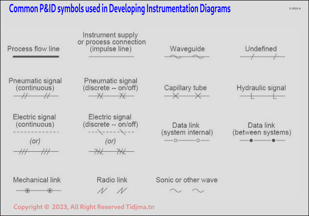
SIGNAL NATURE
The signals received and transmitted by the regulator must be standardized to allow for interchangeability of equipment.
They can be of different nature:
- Electrical
- Pneumatic
- Digital
- Less frequently, hydraulic
These signals are standardized
| ANALOG SIGNAL NATURE | MOST COMMON STANDARDIZED VALUES |
| undefined | |
| electrical | 4<i<20 mA |
| pneumatic | 200<P<1000mb |
| digital | encoded on 8, 16, 32, ... bits |
In electrical (current):
- 0% scale ----> 4 mA
- 100% scale ----> 20mA
In pneumatic (pressure):
- 0% scale ----> 200 mb (3 psi)
- 100% scale ----> 1000mb (15 psi)
In digital, signals are encoded in binary on 8, 16, 32, or 64 bits in serial or parallel communication.

Depending on the nature of the sensors, actuators, and regulators (analog or digital), converters are essential at different points in the loop to standardize signals.
EXAMPLE
Hydrostatic level sensor
Digital regulator (computer)
Automatic valve with analog opening, pneumatic control
PRINCIPLE DIAGRAM OF A COMPLEX REGULATION LOOP

- hydrostatic gauge
- pressure to current converter
- analog to digital converter
- digital to analog converter
- current to pressure converter
- automatic pneumatic control valve
MEASUREMENT SENSORS
A sensor is the element of a measuring device used to acquire information related to the variable being measured.
The sensor is the key element and the first link in a measurement chain.
Its role is to capture and transform the physical variable to be measured (or measurand) and its information content into another physical variable accessible to human senses or the following links in the acquisition chain.
Therefore, they are sensitive organs, transforming the variable to be measured into a standardized electrical, pneumatic, hydraulic, or digital signal, representative of the original information.
This transformation generally requires an external energy supply to the system.
As a rule, the sensor's sensitive element is linked to a translator or transducer that allows the transformation of the displacement or deformation of this sensitive element into a measurement signal or indication.
PRINCIPLE DIAGRAM

For simplicity, the whole assembly is called SENSOR.
PRINCIPLES OF SOME SENSORS
PRESSURE MEASUREMENTS AND SENSORS
DEFINITION: A pressing force F acting uniformly on all parts of a surface S
determines a pressure P such that P = F/S
REMARK: Pressure in a fluid can be expressed as the height of a column of fluid. A pressure measurement can therefore determine the level in a container.11
PRESSURE DESIGNATION:

1, 2: gauge pressure (or effective pressure)
3, 4: absolute pressure
5, 6: differential pressure
PRESSURE IN A MOVING FLUID
- Ps: Static Pressure
- Pd: Dynamic Pressure
- Pt: Total Pressure

LEVEL MEASUREMENTS AND SENSORS
Many different systems are used. It is important to know a number of essential parameters to choose the most suitable sensor, including:
- the nature of the fluid
- the physical and chemical properties of the fluid
- the desired measurement accuracy
- direct or remote indication
- safety conditions
FLOW RATE MEASUREMENTS AND SENSORS
Several techniques can be implemented. Integrating the flow rate over time provides access to counting.
We essentially find:
- volumetric meters
- turbines
- electromagnetic flowmeters, Vortex effect, ultrasonic, mass, target
- Pitot and Prantl tubes
- pressure-reducing elements: orifice plate, venturi, nozzle.
This is part only of our article, the full article will soon be available
Comments