Piping and Instrument Diagrams P&ID
SCOPE
This design gudlines covers the guidelines for the preparation of Piping & Instrument Diagrams for crude oil and gas onshore installations including GOSPs, oil refineries and related processing facilities.
The main types of diagrams covered are Piping & Instrument Diagrams .
Also covered are Distribution Headers, Interconnecting Pipework and Equipment Auxiliary Flowsheets.
The provisions laid down in this specification shall be complied with in full and any exceptions must be authorised in writing by the Owner.
In the event of any conflict between this specification and any of the applicable codes and standards, the Vendor/Contractor shall inform the Owner in writing and receive written clarification before proceeding with the work.
This General Engineering Specification will form part of the Purchase Order/Contract.
DEFINITIONS
Design Pressure
The design pressure is the pressure to which process systems and equipment are designed to withstand the maximum pressure which can occur under the full range of operating conditions including emergency situations.
Design Temperature
The design temperature shall be determined from the maximum operating temperature under the full range of operating conditions, including emergency situations, or normal operating temperature plus 50oF (28oC) whichever is the higher.
GENERAL
Layout
The layouts of the Instrument Diagram (P&ID) shall be typically as shown in the examples in below Figures.
The drawings shall be presented on Metric Standard Size A1 paper.
All flowsheets shall incorporate the following information in the title block:-
Owner Name and Logo, Location, Owner's Contract Number, Vendor's/Contractor's Contract Number and Drawing Number with revision.
The drawing shall include a revision block, showing the revision number (O, A, B, C, etc), date of issue, approval signatures (as required by the Purchase Order/Contract).
All flowsheets shall have a single line border.
Quality
The quality of the originals and reproducibles shall be such that the drawings are legible when reduced to Metric Size A3.
Therefore care must be taken to select suitable font sizes for the original drawing and lines are to be of sufficient density so as to remain clear after copying.
Revisions
Maintain for all revisions a Project Master Copy of the P&ID and Line List with all the latest information included. This is the Master for all personnel working on the Contract.
The original drawings are approved and signed by the Project and Process Engineers and Other Specialist Engineers as appropriate.
Revisions to P&IDs from Rev A onwards shall be shown by encircling the revised portion of the drawing. For definition of issue revision, numerals and letters.
Equipment or data for which information is not available at the time of issue shall be marked clearly with a "hold" designation. This is to ensure that detailed design does not proceed until the relevant information is obtained for the item.
Holds must only be used when absolutely necessary where applicable to P&IDs. Normally all holds are to be resolved prior to the issue of Rev B and are not permitted for Rev C.
PIPING & INSTRUMENT DIAGRAMS (P&IDs)
Scope of P&IDs
This section covers the production of Piping & Instrument Diagrams (P&IDs) and Utility Piping & Instrument Diagrams.
Piping and Instrument Diagrams (P&IDs) are sometimes referred to as Engineering Flow Diagrams, Engineering Flowsheets, or Flowsheets. In this specification, they are to be referred to as P&IDs, and line classification lists will be termed "Line Lists".
These draft P&IDs shall be prepared considering the drawing layout and arrangement so that sufficient space can be allowed for future development.
When P&IDs are not provided by a Licensor, the Process Engineer assigned to the project is responsible for preparing the first draft of P&IDs. The Process Engineer may be substituted by the Project Engineer, dependant on the project complexity.
Check that all items on the Equipment List are included.
The following attachments are included as a guide for the development of the P&IDs:
- Figure No. 1: Typical Piping Symbols
- Figure No. 2: Typical Valve Symbols and Instrument Symbols
- Figure No. 3: Typical General Piping Special Pieces
- Figure No. 4: Typical Equipment Symbols
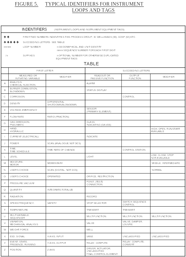
- Figure No. 5: Typical Indentifiers for Instrument Loops and Tags
The item above are not all inclusive and may need adding to, or altered dependant on the complexity of the project and Owner's preference.
The check list for P&IDs serves as a guide to the type of information that shall be included on the drawings.

Issues (example)
Comment Issue P&ID and Line List
This is the first issue containing basic information for Engineering Sections to review and develop. It is suitable for initial plot plan development.
Rev "0" P&ID and Line List
(a) This is the "For Comment" issue and is used primarily for the formal Engineering Review of the P&ID by all engineering groups and by the Owner;
(b) This issue is suitable for plot plan development and for initial piping MTO;
(c) The Line List is completed as required by GES P.01, Section 7.0, on the standard sheet and issued at Rev 0 with the P&ID;
(d) The responsible engineer as required by the Project Execution Plan shall review comments and changes by Specialist Engineers and add to the Master copy together with preliminary Vendor/Contractor information;
(e) The responsible engineer as required by the Project Execution Plan shall check that all information on Rev 0 issue as specified in the Check List has been included;
(f) The drawing original is approved and signed by the Project and Process Engineers and other Specialist Engineers as required by the Project Execution Plan;
(g) Following receipt of the required signatures issue Rev 0 Copy of the P&ID and Line List to the distribution required by the Project Execution Plan;
(h) A Project Master Copy of the P&ID and Line List with all the latest information is maintained by the Lead Project Engineer for reference and to track changes and updates to the drawing.
Rev "A" P&ID and Line List
(a) This is the update issue prior to the "For Approval" issue which is the next update and seeks Owner's approval;
(b) A comprehensive listing, termed a Revision List, is issued with Revision A and subsequent issues of the P&ID. The listing shall include an itemised description of all changes from the previous issue. The listing dates the change and informs the engineering disciplines of alterations included;
(c) This issue contains the Owner's comments, results of the formal Engineering Review, and some Vendor's/Contractor's data;
(d) Detailed Piping Layout work can now commence and it is important therefore that this issue and all later issues have a "Hold" identification system to indicate all information which is not firm;
(e) Update the Line List.
Rev "B" P&ID and Line List
(a) This is the "For Approval" issue, meaning Owner Approval;
(b) This issue is made prior to the model being reviewed, when a model is provided for the project;
(c) This issue contains the remaining Vendor/Contractor data and can be used for the Intermediate piping material take-off;
(d) This issue will normally precede the check of the final piping General Arrangement;
(e) Update the Line List and Revision List.
Rev "C" P&ID and Line List
(a) This is the "For Construction" issue which shows the complete plant as being purchased and constructed. Any remaining Holds have been removed;
(b) This issue may be used for the Final piping material take-off;
(c) This issue incorporates model comments, where a model is used for the project;
(d) Any further revisions will be "As Built";
(e) Update the Line List;
(f) Update of Revision List.
Piping
The Rev 0 P&IDs shall be marked up with all the equipment and line sizes for which information is known.
The Piping Group will check the latest revision of the P&ID against checked isometrics and general arrangement drawings.
Where feasible, the Piping Group shall ensure that all branch lines are shown in the same order as they are actually piped up. A final check shall be carried out when all branch line sequences have been finalised.
For Piping, the following details are shown on the P&ID at Rev 0:
(a) line sizes, numbers and classifications requirements;
(b) insulation symbols, where applicable;
(c) block valves, check valves, bypasses;
(d) start-up and shut-down lines, which shall be distinguished by a lighter line thickness and identified in the notes;
(e) required line slope or special conditions such as vertical loop dimensions, gravity lines etc.;
(f) test vents and drains.
Line List
The Line Lists to show the line sizes, the maximum operating conditions, design parameters, insulation requirements and additional details as required by GES P.01, Section 2.0 is generally finalised to accompany Revision 0 of the P&IDs.

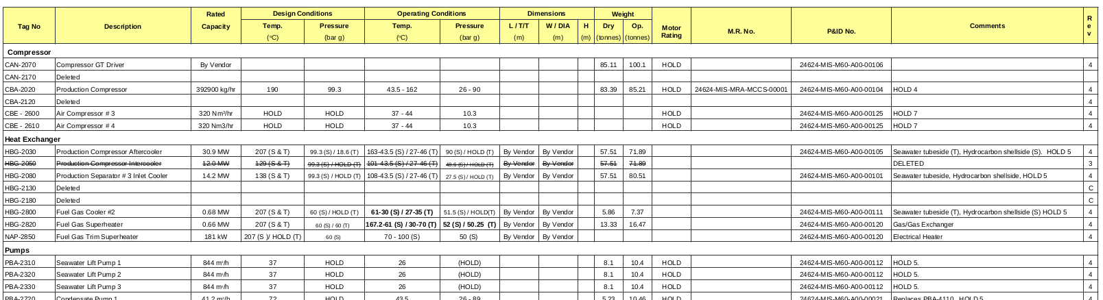
Equipment
The following equipment information shall be included on the P&IDs:
(a) all equipment items, excluding items within packaged units where the Vendor is providing the P&ID for package definition;
(b) sizes of vessels - tan/tan length and diameter;
(c) equipment item numbers and service at the top of the P&ID. The number shall be repeated alongside the equipment;
(d) elevations of equipment above grade, shown at vessel bottom tan line or by an agreed method;
(e) relative elevations of all equipment and piping for gravity or 2 phase flow cases, shown by an agreed method, where relevant;
(f) include all spare equipment and show the common spares;
(g) significant equipment detail which affects piping or instrumentation, shown as special items with numbering system to assist tracking;
(h) all notes for layout;
(i) show cooling water to machinery where used.
A selection of equipment symbols is shown in Figure 4.
Equipent List.
Instrumentation
The P&ID is the master drawing for the instrumentation on the project and therefore all instruments shall be shown on the P&ID.
The following instrument information shall be included on the P&IDs:
(a) all instrument numbers;
(b) all instrumentation except details of complex systems;
(c) safety valves and relief systems.
Do not show the following Complex control systems. It is sufficient to show a box with a brief note referring to the detailed logic diagram.
Instrument symbols and tags shall be in compliance with specification.
Some of the applicable symbols and tags are shown in Figure below.
Safety Reviews
A pre-Rev A issue is prepared and this shall be subjected to a formal review by a team comprised of Authorised Engineers from Project, Process, Commissioning and Instrument Group, or at a time dictated by the Owner or Project Execution Plan.
A hazard and operability study (HAZOP) shall be performed prior to the Rev A issue, if requested by the Owner. The study shall be undertaken by the relevant discipline engineers, including the loss prevention and safety disciplines as required.
OTHER PIPING AND INSTRUMENT DIAGRAMS
Utility Piping & Instrument Diagrams
Utility P&IDs and Utility Line Lists are prepared by the responsible Engineer as required by the Project Executive Plan.
Provided a process package is available for the Utility systems they shall be worked on in parallel with the process package. Issue times for Utility P&IDs should be broadly similar to those for Process Unit P&IDs.
Auxiliary P&IDs
These P&IDs are prepared to show auxiliary equipment associated with major items of rotating equipment. The Mechanical Equipment Engineer carries most of the responsibility for the content of this type of P&ID, since it covers equipment requisitioned by the Mechanical Group.
Because the details of equipment auxiliaries differ depending on the Vendor/Contractor selected, this type of drawing is prepared when the Vendor's/Contractor's drawings for the equipment are available.
Distribution Header Diagrams
Distribution Header Diagrams show the plant piping header systems, and are prepared once the requirements have been shown on the P&IDs, and plot plans have been established.
Offsites Flow Diagrams
Offsites Flow Diagrams show the plant and piping on the offsite areas of the project, and are prepared once the layout of the offsite areas have been defined in sufficient detail.
Offsite flowsheets shall be drawn on a geographical basis with North clearly indicated.
They shall show the same information as required for the P&IDs.
Interconnecting Pipework Diagrams
Interconnecting piping diagrams are used to define the process, utility and offsite lines connecting the various areas of the project. These are usually lines which will be on interconnecting racks or sleepers.
These lines are shown geographically.
They shall show the same information as required for the P&IDs.
Existing lines into which these lines are tied are shown in dotted form.
These drawings are particularly important for the definition of tie-in points to existing lines on the site.
VENDOR/CONTRACTOR FLOWSHEETS
Vendor/Contractor Piping & Instrument Diagrams
These P&IDs are prepared by a Vendor/Contractor of a Package Unit to show the equipment within the package.
The Vendor/Contractor shall provide the P&IDs to the standards set out in this specification.
The P&ID shall show all important information for the Contractor/Vendor interfaces, including the process and utility piping to and from the Vendor's/Contractor's package.
Check List of Information shown on P&IDs
General
These checks apply to all the categories listed in the next sections, unless agreed otherwise by the Owner.
Show in the P&ID equipment block on the drawing:
(a) item number and service;
(b) check flowsheets against Owner's/Licensor's specifications;
(c) design pressure and temperature;
(d) vessel dimension.
Also always show:
(a) equipment elevations for process requirements; for pump NPSH, gravity flow (especially flow to sidestream strippers), thermosyphon reboilers, flow measurement of boiling liquids;
(b) systems into which continuous and intermittent drains discharge;
(c) insulation requirements - type/thickness.
Piping
(a) all line sizes;
(b) full line number for all lines (size-fluid type-number-spec);
(c) show points at which line size changes;
(d) all specification breaks detailing changes in flange ratings;
(e) special piping arrangements, eg no pockets, symmetrical, tangential, special loops, continuous fall in given direction;
(f) process vents and drains. Indicate open or closed drain system;
(g) sample connections (and sample coolers where required);
(h) flushing and slop connections;
(i) purging and venting connections;
(j) blowdown and dropout connections;
(k) pump-out lines;
(l) identification of service for lines leaving unit flowsheets;
(m) future connections;
(n) indicate break between underground and above ground piping;
(o) manual valves; indicate LO, CSO or physical interlock (as applicable);
(p) specify any special requirements such as draining, slope, no pockets, etc.;
(q) line filters, strainers (tag no and indicate whether basket, cone, plate or Y-type) temporary strainers;
(r) spool pieces;
(s) spectacle blinds;
(t) flexible hose connections and size (if part of process);
(u) header identification (show header caps, weld, screwed or blind flanges);
(v) jacketing (steam, water);
(w) extent of chemical cleaning requirements - indicate on line list;
(x) by-passes around equipment for alternate operations;
(y) block valves for relief valves to be shown locked/open;
(z) PSV bypasses;
(aa) corrosion monitoring fittings (types - probes/coupons, etc).
Tracing and Insulation
(a) heat conservation insulation;
(b) steam tracing (indicate where this begins and ends);
(c) steam jacketing (indicate where this begins and ends);
(d) personnel protection insulation;
(e) electrical tracing;
(f) fireproofing requirements for equipment;
(g) show any wire mesh guards for hot lines;
(h) clearly mark uninsulated hot lines.
Instrumentation
(a) all instrument tag numbers; use logical sequential system;
(b) indicate which are local or board-mounted instruments;
(c) all alarm systems;
(d) all trip systems;
(e) all control valves;
(f) indicate control valve failure action (opens, closes or locks);
(g) control valve blocks and bypasses;
(h) sizes of control valve bypasses;
(i) panel and local temperature instruments;
(j) indicate Duplex thermocouples where required;
(k) indicate hand jacks, where required;
(l) show transmission lines, electronic and pneumatic;
(m) location requirements for transmitters (eg above or below line);
(n) identify instruments furnished by Vendors with (v) symbol;
(o) show flowmeter orifice run sizes;
(p) define flowmeter when other than orifice type, e.g. annubar, Dall tube, etc.;
(q) define location of local receiver gauges;
(r) control facilities for compressors, reciprocating pumps, air fins;
(s) show analysers and associated utility requirements;
(t) check sufficient instrumentation provided to measure consumptions for guarantees;
(u) winterisation of instruments - steam or electric;
(v) relief valves, inlet and outlet sizes set pressure and where discharged;
(w) all safety valves and relief lines;
(x) orifice size and flange sizes for relief valves;
(y) set pressure for relief valves;
(z) thermal safety valves (TSVs).
Vessels, Columns and Reactors
(a) vessel size (diameter x t/t length);
(b) nozzle sizes, where different from line size;
(c) manways and handholes with sizes;
(d) elevation of bottom tangent line of datum relative to grade;
(e) slopes of vessels;
(f) identify specification break between vessel and piping;
(g) trays - show number of trays from bottom to top. Also show tray number wherever a connection is made. Do not show all trays;
(h) vessel internals - vortex breakers, baffles, coils, demisters;
(i) column internals - distributors, vortex breakers, baffles, internal pipes, coils;
(j) reactor internals - distributors, grids, beds;
(k) location of relief valves/vacuum breakers;
(l) testing facilities (eg spectacle blinds);
(m) catalyst loading and unloading facilities;
(n) facilities for catalyst regeneration and effluent disposal;
(o) external firewater sprays;
(p) mixers/heaters;
(q) vents, drains, pump-out and steam-out connections;
(r) sewer type for each drain (oily water, clean water, chemical, etc).
Tanks
(a) tank size (diameter x height, volume);
(b) nozzle sizes;
(c) type of roof (fixed, floating, etc);
(d) manways and sizes;
(e) base elevation relative to grade;
(f) tank internals - vortex breakers, coils, baffles;
(g) overflow line;
(h) relief valves/vacuum breakers;
(i) gauge hatches and sampling connections;
(j) testing facilities (eg spectacle blinds and line spacers);
(k) firewater spray protection systems;
(l) mixers/heaters;
(m) vents, drains, pump-out and steam-out connections;
(n) dewer type for each drain (oily water, clean water, chemical, etc).
Heat Exchange Equipment
(a) shellside pressure drop;
(b) tubeside pressure drop;
(c) surface area/Shell Dia/Tube length;
(d) number of shells for exchangers;
(e) specification breaks as applicable to multiple units;
(f) driving head for reboilers (difference in elevation between tangent line of column and top of reboiler);
(g) chemical cleaning connections and inhibitor injection;
(h) nozzle sizes where different from line size. Number of nozzles;
(i) temp and press gauges on nozzles;
(j) testing facilities - isolating flanges, blinds, vents and drains (with sizes);
(k) header configuration for air coolers;
(l) louvres for air coolers - manual or auto;
(m) autovariable hubs (AV hubs) with controls;
(n) air-fin combinations;
(o) winterisation (air coolers) - steam or electric;
(p) number of bundles for air cooler;
(q) vibration switches;
(r) number of fans on auto variable control;
(s) steam coils on air-fin coolers.
Furnaces
(a) duty and Surface Area;
(b) tubeside pressure drop;
(c) number of passes;
(d) hydrostatic test facilities (blinds, vents, drains);
(e) relief valves for blocked conditions;
(f) pass flow control arrangement;
(g) skin point TI location;
(h) TIs for combustion space, radiant and convection sections and stack draught gauges;
(i) draught gauges and sampling connections;
(j) steam snuffing and decoking connections (firebox and header boxes);
(k) burner piping and control system;
(l) igniters and flame failure protection;
(m) damper - manual or remote control;
(n) ducting, dampers and stack arrangement;
(o) FD/ID fans;
(p) air preheater;
(q) soot blowers, Auto or Manual. Show break between Contractor and Vendor's supply;
(r) steam/air decoking and regeneration facilities;
(s) check that all services and utilities required are included.
Pumps and Drivers
(a) show by symbol the type of driver and type of pump;
(b) pump pressure rating;
(c) design differential pressure;
(d) dumping temperature;
(e) specific gravity at pumping temperature;
(f) pump flushing arrangement;
(g) vents and drains (sizes) when they are piped up;
(h) pump suction strainer and type;
(i) winterisation, steam or electric;
(j) automatic start-up of standby unit;
(k) relief valves for positive displacement machines (indicate Vendor supply);
(l) warm-up lines;
(m) sizes of suction and discharge valves and pump nozzles;
(n) rating of pump flanges;
(o) ensure non-return valve shown;
(p) pressure indicator on discharge;
(q) service and utilities including cooling medium to bearings, mechanical seals, etc;
(r) lubrication system (use symbol to specify);
(s) minimum flow recirculation system;
(t) turbine piping and drainage arrangement for auto or manual start.
Compressors and Drivers
(a) show by symbol type of compressor and type of driver;
(b) design capacity;
(c) design differential;
(d) suction and discharge valves and blinds;
(e) location of relief valves;
(f) suction filter and tag number;
(g) winterisation steam or electric;
(h) vents and drains with sizes;
(i) lube oil system;
(j) machine cooling system;
(k) gas coolers, including interstage;
(l) sizes of compressor inlet and outlet nozzles valves and rating (only if different from line);
(m) start-up facilities (e.g. by-pass type);
(n) purging facilities;
For Centrifugal Machines
(a) compressor anti-surge controls;
(b) seal and lube oil systems (separate flowsheets).
For Reciprocating Machines
(a) suction and discharge pulsation dampeners;
(b) seal chamber and distance piece vents;
(c) packing vent system.
Utility Equipment
The utility flowsheets follow the same format as the P&IDs:
(a) include all relief valves for blocked conditions;
(b) show all operating vent and drain lines;
(c) show all services required on drawing;
(d) show clearly extent of Vendor's supply;
(e) show basins, pits, channels etc where part of plant.


Comments
Patric
on May 17, 2025 at 2:54 p.m.Great!
Monzark
on May 17, 2025 at 2:56 p.m.Insightful