Pipeline Cathodic Protection System
APPLICATION OF CATHODIC PROTECTION
Although the basic theory of cathodic protection is very simple - making the entire surface of the structure a cathode - it is necessary to be able to determine when cathodic protection has been achieved and corrosion eliminated from the structure. Over the years various criteria have evolved, but the most practical method of evaluating cathodic protection is by measuring the pipe/soil potential, as this is directly related to the current density being received on the pipe surface.
When planning a cathodic protection system a number of questions need to be resolved:
- How much current will be required to protect the structure:
(a) initially
(b) at the end of the structure life?
- How should the system be designed?
- Which system should be used?
- What distance between installations?
- What testing, commissioning and monitoring facilities will be required?
In order to answer some of these questions it is necessary to obtain information about the structure and the environment, including:
- Is structure bare or coated?
- If coated, what type of coating system, quality, electrical resistance, inspection standards etc.?
- Diameter and wall thickness of pipeline?
- What grade of steel is used?
- Presence of other metallic structures crossing or in close proximity to the pipeline.
- Soil types and resistivities
- Any known corrosion history in the area
- Availability of a.c. supplies
- Presence of any other cathodic protection systems of sources of stray currents that could interfere with the system being designed.
It can be seen therefore that a considerable amount of effort and thought is required in determining the needs and design of a cathodic protection system. The following table shows a comparison of the advantages and disadvantages of each cathodic protection system.
A COMPARISON OF SACRIFICIAL ANODE AND IMPRESSED CURRENT SYSTEMS
| SACRIFICIAL ANODES |
| IMPRESSED CURRENT |
1 | They are independent of any source of electrical power | 1 | Requires a mains supply or other source of electric power |
2 | Their usefulness is generally restricted to the protection of well-coated structures or the provision of local protection, because of the limited current that is economically available. | 2 | Can be applied to a wide range of structures including, if necessary, large, uncoated structures. Large currents can be provided. |
3 | Their use may be impracticable except with soil or waters with low resistivity. | 3 | Use is less restricted by the resistivity of the soil or water. |
4 | They are relatively simple to install; additions may be made until the desired effect is obtained. | 4 | Needs careful design although the ease with which output may be adjusted allows unforeseen or changing conditions to be catered for. |
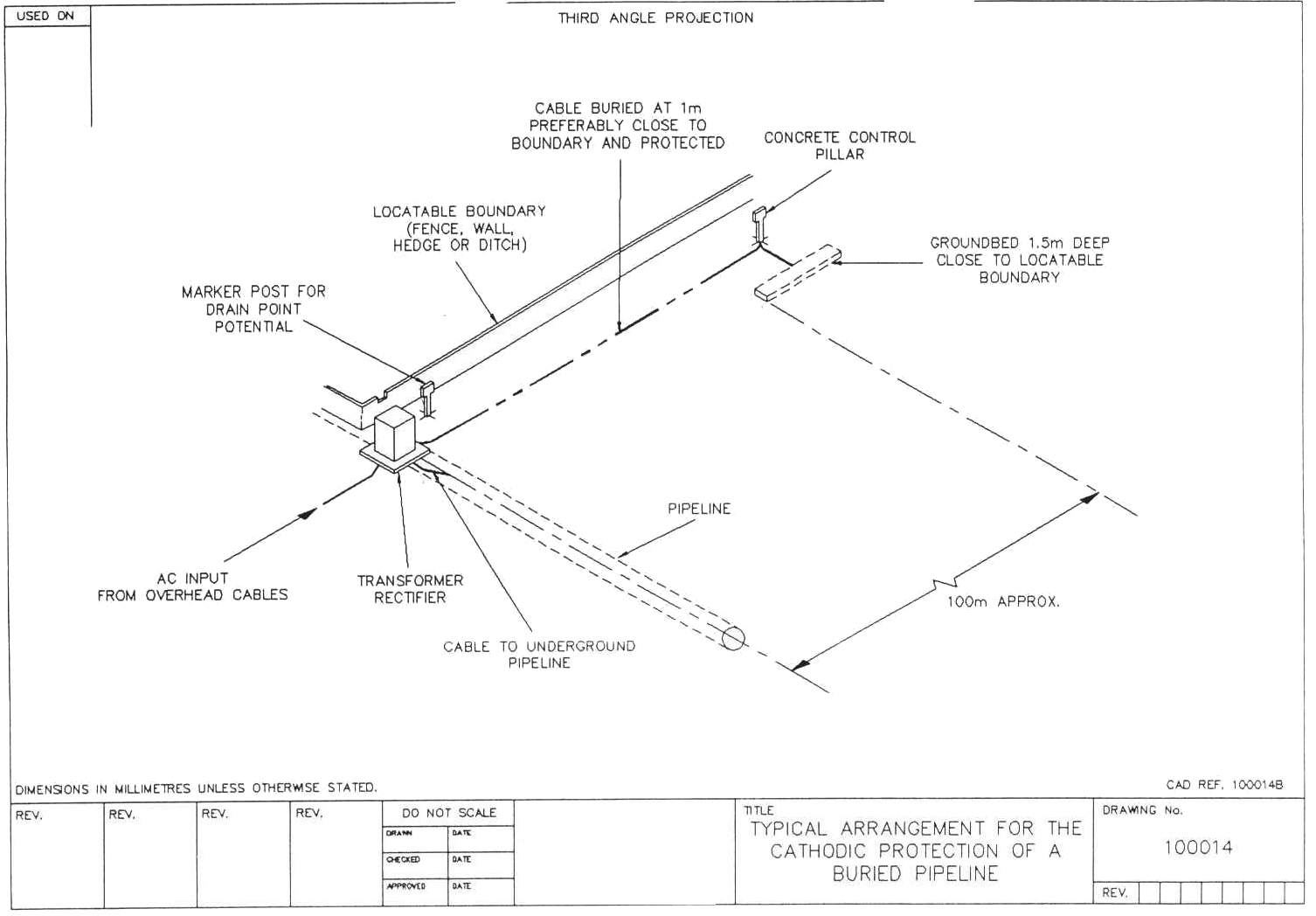
5 | Can be installed within the pipeline easement. | 5 | The groundbed must be a minimum of 100m from the pipeline - a separate easement must be negotiated. |
6 | Inspection involves testing, with portable instruments, at each anode or between adjacent pairs of anodes. | 6 | Needs inspection at relatively few positions; instrumentation at points of supply can generally be placed where it is easily reached. |
7 | They may be required at a large number of positions. Their life varies with conditions so that replacements may be required at different intervals of time at different parts of the system. | 7 | Requires generally a small total number of anodes. |
8 | They are less likely to affect any nearby neighbouring structures because the output at any one point is low. | 8 | Requires the effects on other structures that are near the groundbed of protected structures to be assessed, but interaction is often easily corrected, if necessary. |
9 | Their output cannot be controlled but there is a tendency for their current to be self-adjusting because if conditions change such that the metal to be protected becomes less negative, driving voltage and hence current, increases. It is possible, by selection of material, to ensure that the metal cannot reach a potential that is sufficiently negative to damage paint. | 9 | Requires relatively simply controls and can be made automatic to maintain potentials within close limits despite wide variations of conditions. Since the voltage used is generally higher than with galvanic anodes the possible effects of ineffective control or incorrect adjustment, for example, damage to paintwork or coatings, are greater. |
10 | Their connections are protected cathodically. | 10 | Requires high integrity of insulation on connections to the positive side of the rectifier which are in contact with soil or water: otherwise they will be severely corroded. |
11 | They cannot be misconnected so that polarity is reversed. | 11 | Requires the polarity to be checked during commissioning because misconnection, so that polarity is reversed, will accelerate corrosion. |
In practice the choice of system is generally as follows:
Sacrificial Anode
- Small structures
- Short pipelines
- Urban areas with large numbers of other services
- Water tanks
- Offshore structures
- Submarine pipelines
- Small ships and boats
Impressed Current
- Large structures
- Long pipelines
- Bare structures
- Tank storage depots
- Well casings
- Jetties and harbours
- Offshore structures
- Large ships and tankers
EQUIPMENT
Anodes:
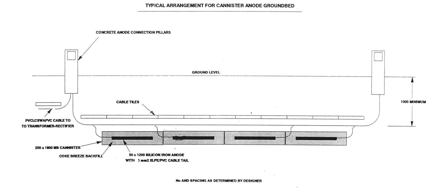
Most land based anodes are used as a method of electrical connection to a bed of carbon (coke). The coke breeze or carbonaceous backfill serves two purposes:
Prolongs anode life.
Allows convenient construction of a long anode with a large surface area giving a low groundbed to earth resistance. (Energy costs of operating the system are directly related to circuit resistance).
Anodes are usually chosen from the following types:
Graphite Anodes: Usually rod form and impregnated with linseed oil. Relatively light but fragile.
High-Silicon Iron: Usually rod form. Heavy and brittle.
Magnetite: Smaller than silicon iron. Relatively light. Long life.
Scrap Steel: Inexpensive. Easily fabricated. Difficult to ensure connection integrity. High wastage rate.
With the exception of scrap steel, all anodes are provided with factory made encapsulated cable connections and cable tail to specified length.
Groundbed Construction
Types: Shallow horizontal
Shallow vertical
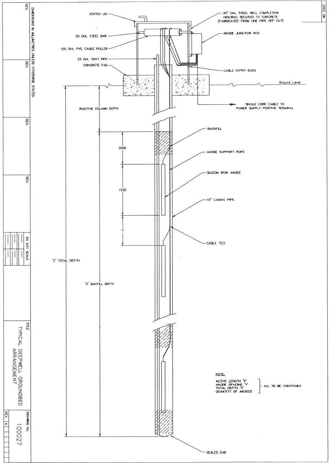
Deepwell or Borehole
Distributed shallow horizontal/vertical single anodes
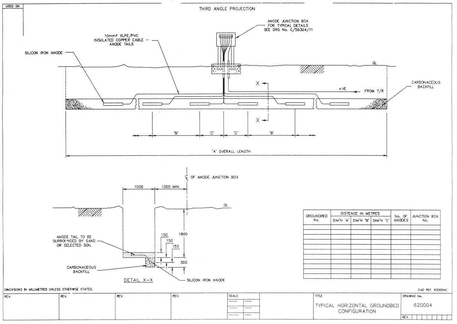
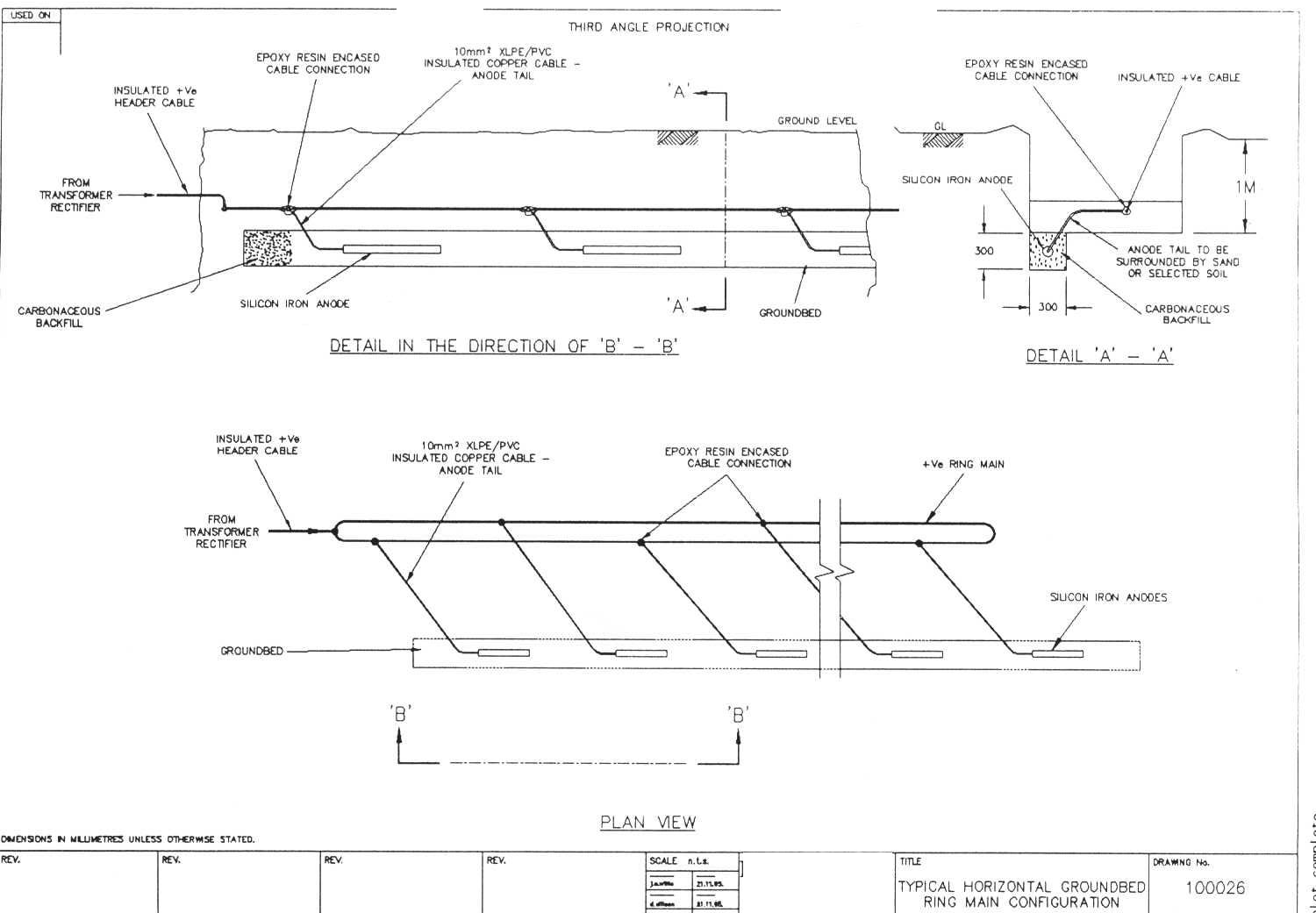
In general, most groundbeds are of the shallow horizontal type, as shown in Figs. 1 & 2. where surface soil resistivities are suitably low. In areas of very high surface resistivities, e.g. desert areas, then deepwell groundbeds will very often be used.
It is essential that all buried cable connections are fully encapsulated and watertight. Whenever possible connections should be made above ground in a connection pillar or anode junction box.
Power Supply
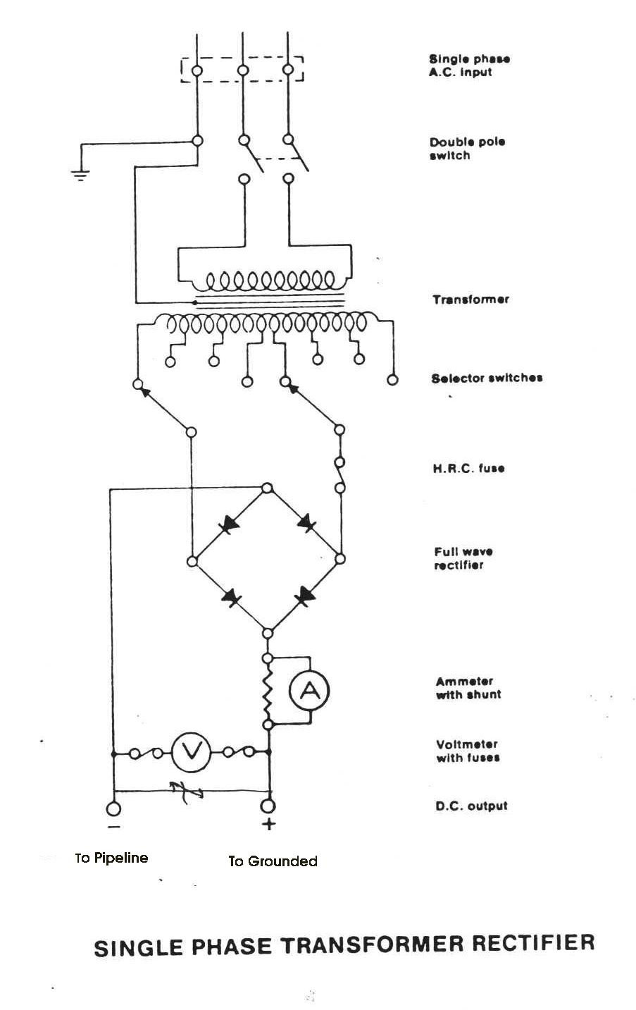
In general the power supply for an impressed current cathodic protection system is a transformer-rectifier with the a.c. being provided from a local electricity supply:
Types: Oil or air cooled
Pole, plinth or wall mounted
Switch, link or Variac control
Automatic constant current or constant potential
A typical schematic diagram of a single phase transformer-rectifier with tapping switches.
Other types of power supply used, in areas where a local a.c. supply is not available, are diesel generators, solar-electric generators, thermo-electric generators and wind generators. These are rarely used in the UK as they are costly and a.c. supplies are readily available but are common on cross desert pipelines.
Isolating Joints:
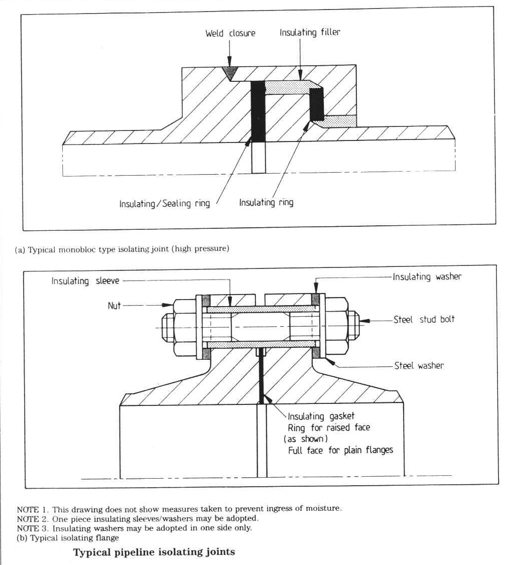
When applying cathodic protection to a pipeline system, it is necessary to limit the extend of the protection and ensure that only the pipeline is protected and not every piece of buried metal in the neighbourhood. This can be achieved by inserting isolating or insulating joints into the pipeline at the limits of the cathodic protection system.
Isolating joints may be used for:
- To separate the pipeline into discreet sections
- Isolation of separate CP systems
- Isolation from hazardous areas
- Restriction of CP to certain areas
- Separation of coated and bare sections
- Isolation from electrical earthing systems
- Restriction of stray or induced currents
Types available are:
(a) Conventional flanged joints using an insulating gasket, insulating sleeves over studs and insulating washers under each nut and steel washer. The completed joint should be wrapped to prevent the ingress of water and dirt.
(b) Monobloc joints are factory made and tested, and welded directly into the pipeline. They have no other use than electrical isolation.
(c) Insulated couplings used for small bore and instrumentation piping.
Grounding Cells:
For safety reasons, it is often necessary to install polarisation cells (either chemical or solid state), zinc grounding cells or static earth cells across an isolating joint to prevent a hazardous build-up of static electricity, or to protect against induced voltages and currents or lightning strikes (see Fig. 6). The grounding cell will conduct electricity at a certain voltage level which is above the levels normally experienced with cathodic protection, thereby maintaining the integrity of the isolating joint, but removing hazardous voltages.
Test/Monitoring Facilities:
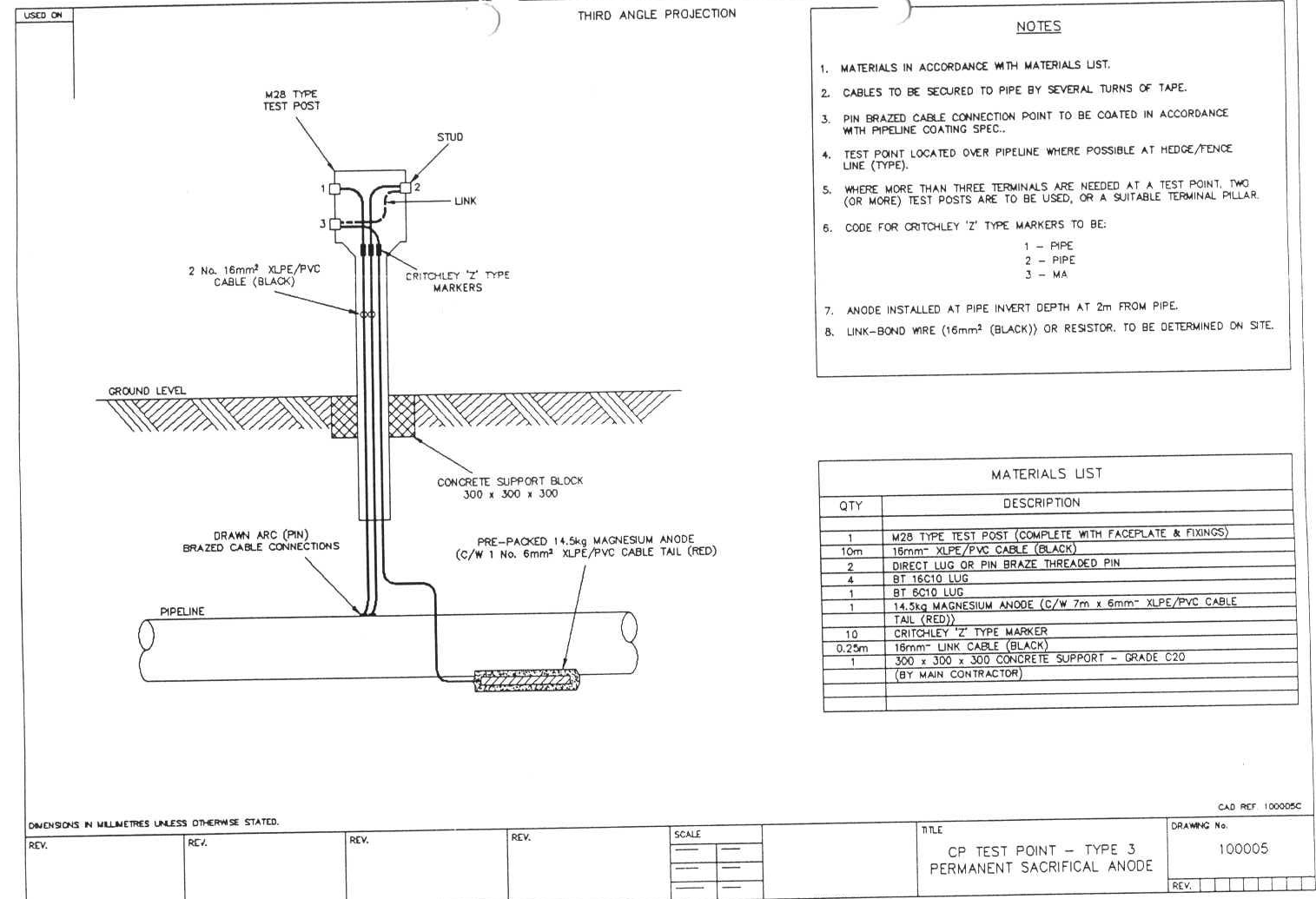
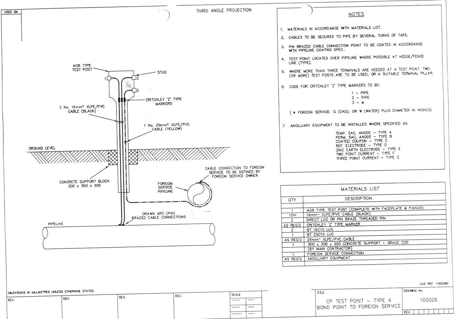
It is essential to be able to monitor the effectiveness of the cathodic protection system. In order to be able to measure pipe/soil potentials it is necessary to make electrical contact with the pipeline. This is achieved by attaching a cable to the pipeline and terminating in a test point as shown in Figs 7 & 8.
Test points are located at approximately 0.5 mile intervals at road crossings, track crossings, field boundaries, etc., where access is easy and likelihood of damage is minimised.

Kimo
on Nov. 29, 2023 at 11:16 a.m.Thanks for sharing